Digital current loop
Uses current rather than voltage level to signal bits.
Absence of current - space or break
Presence of current - mark
Modern loops use 2 different current levels
easier to detect and measure.
easy to identify broken loop.
Uses a single line to transmit data,
but needs a return path for energy sent.
May use a second 'ground' line.
May just ground the signal.
Useful for medium range data transmission 10s of kilometers.
Useful to interface with non-electronic end points.
Reading input from sensors.
Drive punch devices.
Drive multiple printers.
Used for early serial teleprinters.
Required interface to voltage signaled devices.
Fiber has largely replaced it for distance when purely electronic.
Single-ended signaling
Voltage level signaling.
Uses single line to transmit data.
Requires a method of terminating or disposing of singl signal once received.
Common ground most commonly used.
Requires 1 additional line which can be shared by several signal lines.
Original PC system bus for computers.
RS-232, PS/2 (keyboard,mouse), VGA, Parallel ATA (hard drives) -
Point to point connections.
TTL logic, CMOS logic - use a shared ground line/plane system.
PCI bus, SCSI - shared buses.
Others.
+ Cheaper.
- Because reference source is usually shared, more sensitive to cross-talk.
Electrical termination
"In electronics, electrical termination is the practice of ending a
transmission line with a device that matches the characteristic impedance
of the line. This is intended to prevent signals from reflecting off the
end of the transmission line. Reflections at the ends of unterminated
transmission lines cause distortion which can produce ambiguous digital
signal levels and mis-operation of digital systems."
Electrical termination - wikipedia
Historical system buses were designed so that circuits at the end of the
bus lines transferred transmitted signal to ground (TTL logic).
Secondary buses (SCSI) may provide multiple tap points which don't
have to be filled.
So, signal may travel past the last active tap and reflect off of the
end of the bus.
Reflection
Causes interference with subsequent bits.
Can amplify signal and cause damage.
To avoid signal reflection, termination is used.
Check out forums.anandtech.com/threads/active-vs-passive-terminator.814339/
Passive termination - resistor that grounds signal without shorting the
bus line.
Inexpensive but prone to data errors.
Commonly used on earlier SCSI protocols
Active termination - voltage regulator that keeps signal in limited range.
More expensive but better performance.
Used on later, faster SCSI protocols.
Forced perfect termination - uses a pair of diodes and a resistor to
hold bus line in proper voltage range.
Reflected-wave switching
It is possible to take advantage of reflected waves to amplify a weak signal.
If pulse-width of bit is long enough for it to start reflecting back on
itself while still passing the target circuit, the strength of the bit's
signal sums.
This allows bits to use less power,
But restricts the length of the bus, the speed, and the number of 'taps'.
Sending circuitry handles termination of bounced signal.
PCI bus, VMEbus (still in use)
Differential signaling
Primary alternative to single-ended signaling.
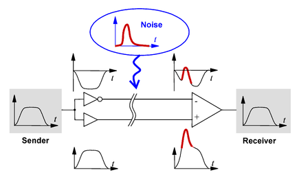 Each signal 'lane' uses a pair of lines.
A signal and its complement are applied to each line.
The lines are terminated by a differential receiver.
The receiver measures the difference between the 2 signals to find the bit.
Noise introduced in the signal lines tends to have same bias and gets
canceled at the receiver.
Also net charge difference between two lines in null.
Independent of encoding - supports either NRZ or NRZI type encoding.
+ more immune to external corruption such as cross-talk.
- requires a pair of lines for each lane
and circuitry to encode and decode the differential signal.
Ethernet, SATA, USB, etc.
Each signal 'lane' uses a pair of lines.
A signal and its complement are applied to each line.
The lines are terminated by a differential receiver.
The receiver measures the difference between the 2 signals to find the bit.
Noise introduced in the signal lines tends to have same bias and gets
canceled at the receiver.
Also net charge difference between two lines in null.
Independent of encoding - supports either NRZ or NRZI type encoding.
+ more immune to external corruption such as cross-talk.
- requires a pair of lines for each lane
and circuitry to encode and decode the differential signal.
Ethernet, SATA, USB, etc.